
This is the home page of the A600 – my 2x MRF300 600W linear amplifier project for HF/6m, as initially described in this article. Here I will post the latest developments.
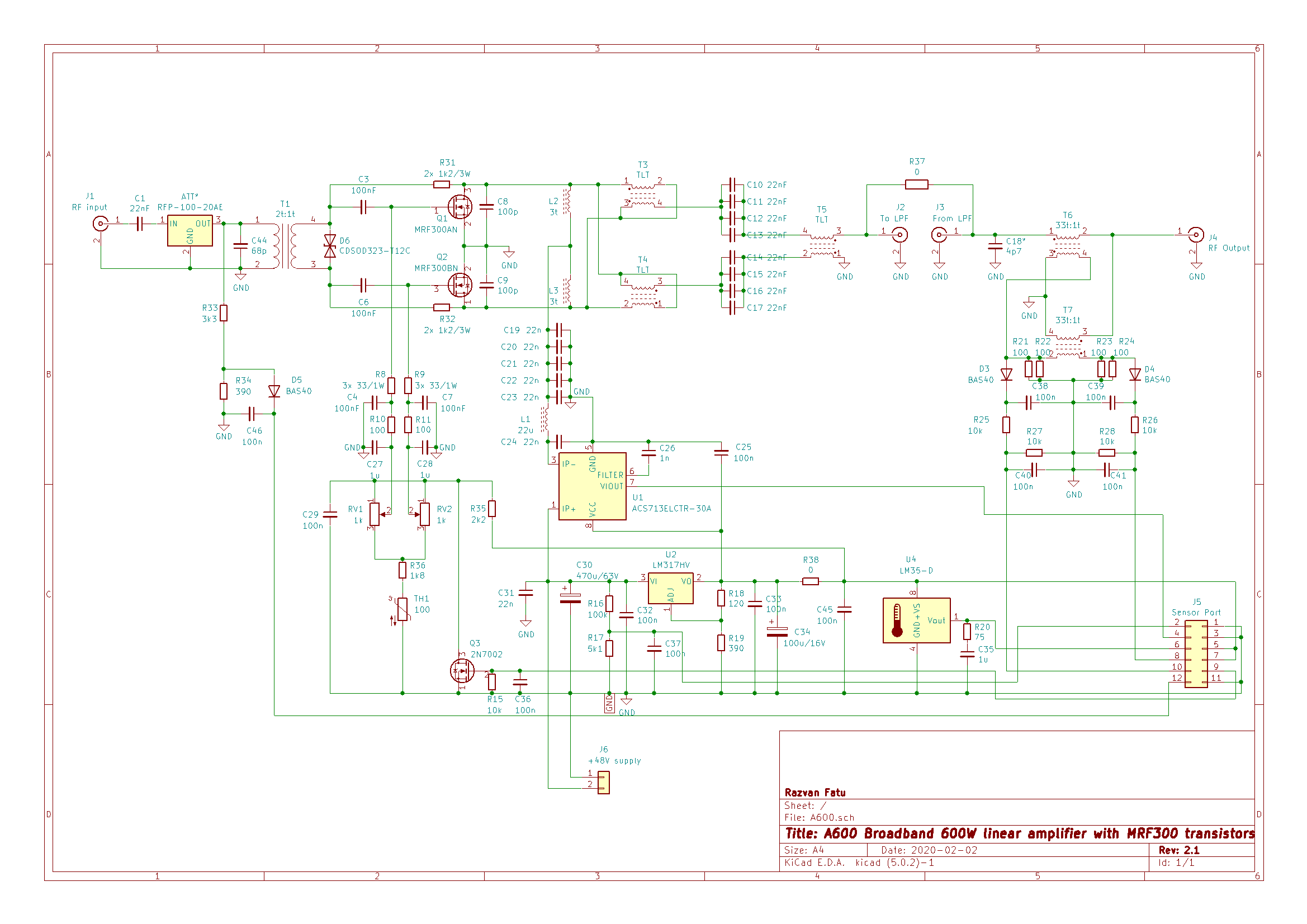
General features & specifications
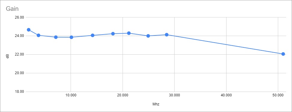
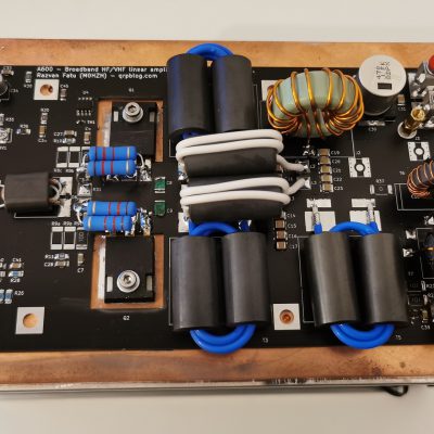
- 1.8-72MHz coverage, 600W output, 20+dB gain
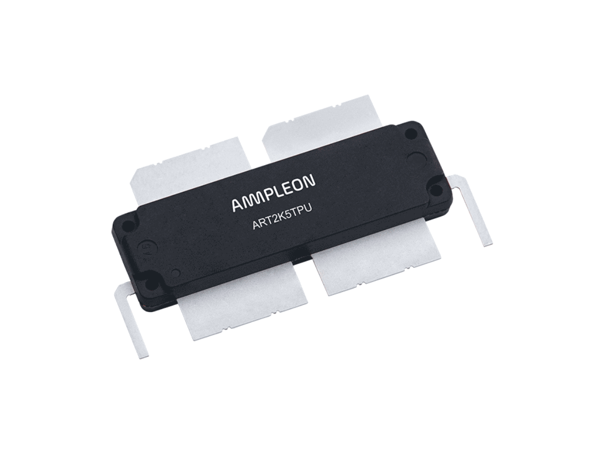
- uses a pair of low-cost MRF300 LDMOS transistors. These are proper RF power transistors housed in common TO-247 packages.
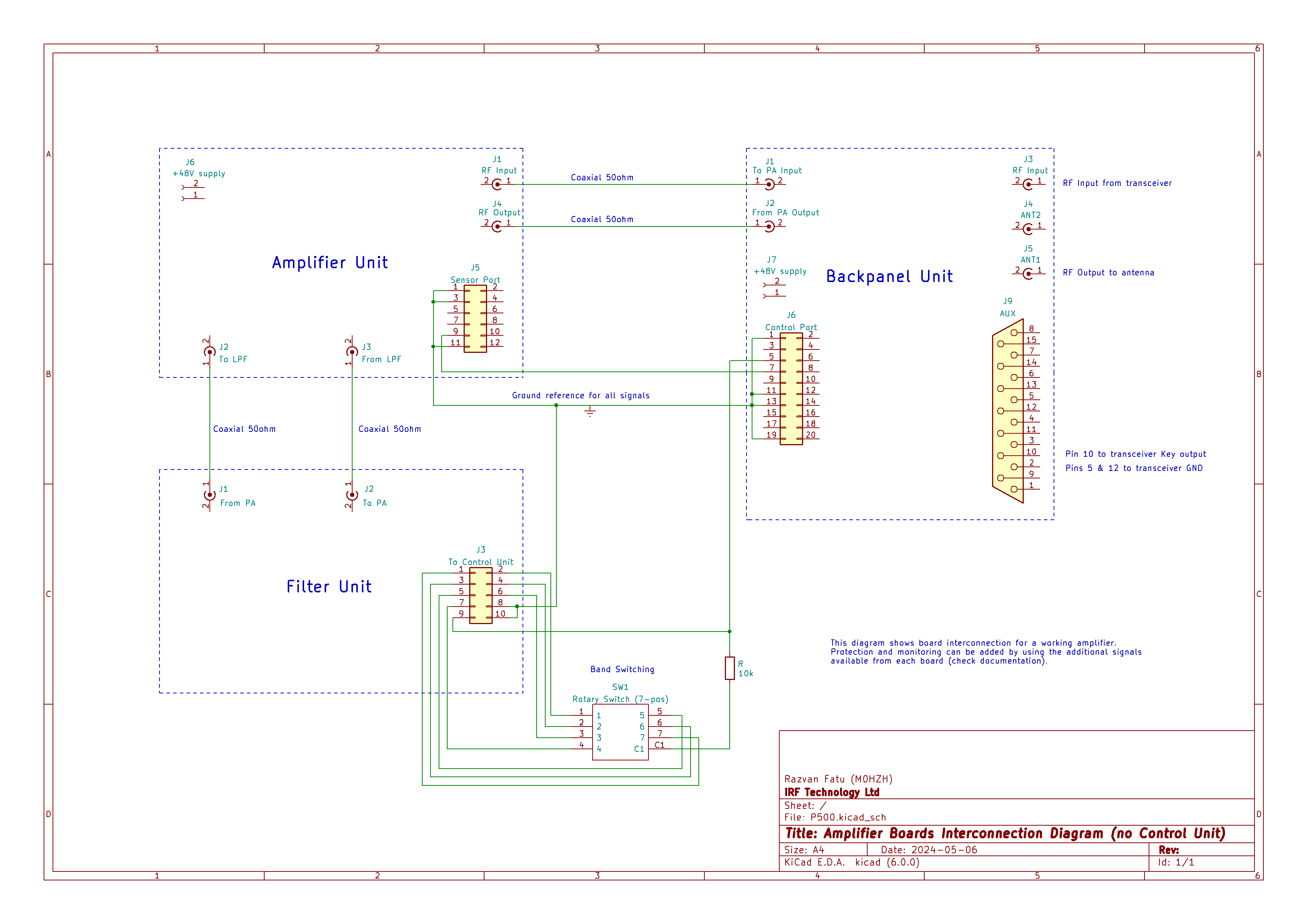
- onboard sensors for supply voltage, supply current, heatsink temperature, output power & reflected power, drive power. These are available via the Sensor Port and can be read directly by most microcontrollers, including most Arduino boards.
- connectors for an external bank of low-pass filters, so they are inserted between the amplifier and the output coupler
Resources
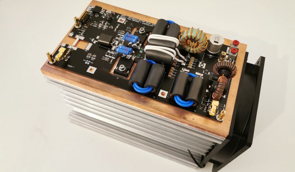
- Article: Choosing a heatsink for the A600 LDMOS linear amplifier
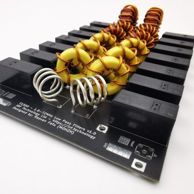
- Article: A 600W Low-Pass Filter Board for 1.8-72MHz
Update – 23rd September 2022
- After many delays related to parts availability and manufacturing challenges, the A600 kit is again available. Version v2.3 brings small changes, most significant being current sensor output; performance, layout remains the same.
- Once again all kits (A600, F1500, B1500) can be ordered from the Shop area and will be shipping from stock, typically next working day.
- Component costs have unfortunately affected overall prices, which had to go up.
Update – 3rd March 2021
- F600 LPF Unit kit has been replaced by the new F1500 LPF Unit, offering higher power handing (1500W PEP) in a very similar package
- All kits (A600, F1500, B1500) are shipping from stock, typically next working day. Check out the Shop area.
- After the recent changes cause by the UK leaving the European Union, all deliveries outside the UK will have to include a customs declaration with attached commercial invoice. Also, prices are now expressed in GBP instead of USD, but you will still be able to pay in any currency via Paypal. The currency conversion will be automatic.
Update – 22nd March 2020
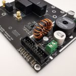
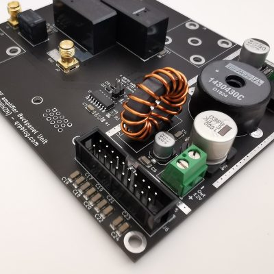
- The B1500 RF amplifier Backpanel Unit is now available. It features RX/TX switching, 2-port antenna switching, transceiver interfacing and has an onboard 12V DC-DC converter.
Update – 22nd February 2020
- After a long delay related to challenges with China logistics, a new revised version of the A600 Amplifier Unit is back in stock. v2.1 brings improvements in ruggedness and is available to order here.
- The Backpanel Unit is almost ready as well and will be announced soon.

Update – 24th December 2019
- LPF board kits are on the way and will ship after 6th of January; two thirds of the first batch are already gone. Can be ordered here.
- A new Backpanel unit is in the works. It will handle RX/TX switching, transceiver interfacing and includes a 12V/3A DC-DC converter and a 2-port antenna switch. Expected in the 2nd half of January.
- This has pushed the Control Unit further back. I know this unit is expected by many of you, but it’s worth the wait as it will support all the features added by the Backpanel Unit.
Update – 7th December 2019
- A600 v2.0 kits now available, includes multiple improvements. More details here, order the new kit here.
- LPF board sent to production, kits will be available soon.

Update – 2nd December 2019
- Published assembly instructions for the v1.2 kit, see above.
- LPF board is still under testing; the prototype achieves the desired attenuation but I’d like to improve insertion loss on a few bands before I release the design and make the kit available.
Update – 20th November 2019
- Assuming no further issues, the next batch of A600 amplifiers will be ready to ship in the first week of December. Includes some tweaks.
- I started working on a compatible Low-Pass Filter board. Should be ready early December.
- Still on track with the Control Unit for mid December announcement. The hardware is almost done but sorting out the software takes time.
Update – 15th November 2019
A600 v1.2 kit was available to order here. Sold out in less than 8 hours so new batch on the way, hopefully by the end of November.
Updates – 14th November 2019
- This project has been awarded the 2nd prize in the NXP Homebrew RF Design Challenge 2019. Really appreciate the opportunity and congratulations to veteran Jim WA2EUJ and the Stanford University team led by Weston Braun for their results.
- Kits are almost ready but some parts are delayed due to courier issues. I plan to start taking orders in the following days and ship out after 20th of November.
- An advanced monitor, control and protection unit is in the works, featuring a large LCD touchscreen. ETA mid December 2019.
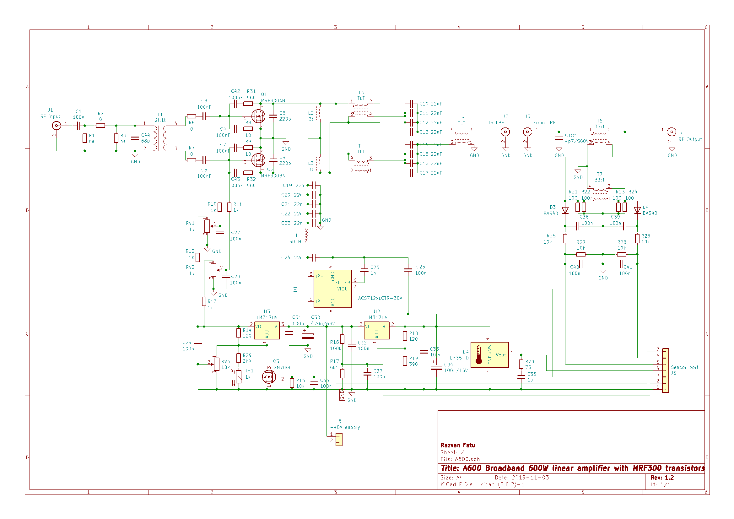
A600 version 1.2
- returned to original component references, as used on v1.0 PCB
- replaced T2 transformer with two separate coils (L2 & L3), 3 turns on ferrite cores. This improves efficiency and P1dB below 14MHz, but 1.8MHz matching is slightly worse.
- changed input network (C43, T1, R6 , R7) for better overall gain (around 24dB now) and better matching on 50Mhz. Input SWR is now below 1.5:1 on all bands.
- added 2k4 resistor in series with the bias compensation thermistor, as it was overcompensating. Quick test, heating the heatsink from 25 to 45C changed the idle current with less than 2%.
- fixed a few small mistakes in the schematic and rewired the Sensor Port to the correct pinout.


Very nice project Razvan.. congrats on results. Had some ideas to get similar power from mrfx600hr5, but your project seems to be a winner . PCB looks great, and just hope to see possibility of getting some form of KIT, or PCB for PA board.
Best regards!
Thank you Robert. Will let you know when kits are available.
I would like to know when they are available also.
73
This is an awesome project! I would definately be interested in a kit.
Add me to the list of hams interested in a kit. I would add an output filter to get that third harmonic (as described in the video) a little lower than -45 dB, but that should be easier.
Very nice. Do you have a kit. I would love to build.
Larry kd6eug
Looks great Razvan, thanks for your efforts! Also very interested in a kit.
Dave K4ZS
Sorry for the multiple posts, I was obviously doing it wrong at first. Please delete!
Thanks, Dave K4ZS
I too would like a kit.
Also interested in a kit! I’ve signed up for alerts too.
Awesome project, if it comes in a kit form I will be selling my children to purchase one.
Professionally done with a great write up. I’m very interested in a kit version.
Nicely done, clean efficient engineering. Thank you for sharing your efforts! I am looking forward to availability of a PCB and BOM. Curious to know if you be working up designs for t/r relay and or band pass filters for this amplifier design?
Great design, I’ll be very interested in a kit version, or even the pcb.
I’m very interested in a kit version.
Great design, I’ll be very interested in a kit version, or even the pcb.
BOM and PCB for me as well, even two 😉
Let me know, nice work.
I too would like a kit.
Also interested in a kit!
Would be interested in further developments too and if you will ever deploy a kit
Looks great, please add me to the list of those that would be interested in a kit!
Andrew G0MBL
Looks great I am also interested in a kit. Is there a mod so it works with a 10-15 w input?
Hi Ted. There is provision on the PCB for an attenuator, you’ll have to choose parts depending on the drive power you want.
Looks very hopeful for us less informed HAMS , several of the guys were talking about a two pallet amp. with a combiner for near legal limit , that would be great , best of all it would be nice to be able to deal in the English language , Thank You RaZvan .
Nice project. Do you have the Gerber-files available so I can order the PCB?
Sorry Fokko, no Gerber files available. But I offer kits with the boards pre-populated and it’s probably cheaper than you can make it yourself, check out the Shop area.
Hello Razvan are there any possibility to order the circuit boards only from you?
Hi Marko,
Sorry, only complete kits are available for now.
The output power exceeds the total Device Dissipation (272W), the ice becomes very thin here!
The efficiency is quite good on these new LDMOS, device thermal dissipation is around 200W.
Hi,
Input transformer (T1) 4:1 and
Output transformer in a ratio of 1:9.
Doesn’t this cause an impedance problem for transistors?
73
Not at all; there isn’t much interaction between the input and the output sections.
Typically, the FET input characteristic is equivalent to a very high value resistor (in the Mohms range) paralelled to a significant capacitor (~403pF for the MRF300). To achieve good broadband response, a low value resistor (10ohm on each gate is a typical value) is used to dampen the reactive effects of the gate capacitance. The input transformer has to match to the combined impedance presented by this resistor and gate capacitance and most of the drive power is actually wasted in the resistor(s).
The output matching is mostly related to supply voltage and desired output power, as the supply voltage limits the maximum amplitude you can have in the output transformer’s primary. Assume 50V supply; this will allow you about 96Vpp primary amplitude (a few V drop caused by FET RdsON) which equals to about 68Vrms. Step that up with a 1:4 transformer (1:2 winding ratio), you will get 136Vrms which is 50ohm is about 370W of output power; with a 1:9 transformer (1:3 winding ratio), the output voltage will be 204Vrms, or about 830W maximum RF power; for more than that, 1:16 (or two 1:4 in series) will be needed. These are not hard limits as the signal coming out isn’t a perfect sinusoid, but useful reference points. There are also some reactive components not taken into account (drain capacitance, transformer inductance, etc) for the sake of simplification.
Let me know if that makes sense. Cheers !
Hi,
Thank you very much for this significant information.
I understand better now.
Do you have any documents you would recommend about the calculation of these output transformers (1: 4 or 1: 9)?
It is not possible to find coax cables other than 50ohm here.
Is there any other way to do this?
Finally;
How to calculate the cable length of 1: 9 transformer and 1: 1 balun at the output?
thank you very much again.
73
The transformer type is called TLT, or “Transmission Line Transformer”. A Google search for “TLT RF power transformers” should come back with more detailed information.
You can paralel coaxial cable to achieve lower characteristic impedance; 2x 50ohm lines of equal lengths will be have 25ohm characteristic impedance, 3x 50ohm lines will have 16.66ohm etc. People typically use RG-316 in this case, but you will need larger ferrite cores to acommodate the extra wiring.
For the 1:9 transformer, ideally the coax length should stay under 1/10 of the wavelength at the maximum frequency of use; the shorter it is, the better the symmetry and the lower the reactive components.
For the 1:1 output balun, choking impedance is the most important factor. Make sure the cores provide enough at the lowest frequency of use.
Good design. Congrats. I will order a kit. Are the coax cables for the transformers in the kit? What is your delivery time?
Hi Peter. Yes, kit has all the electronic parts; you will need a heatsink, mounting bolts, thermal paste etc. These days I post twice a week, but there are some delays with the postal system. Usually it takes about a week to get to European countries.
Razvan.
I’ve been following your amplifier design Razan congratulations on a great kit. What control circuit do you use to monitor al the various functions?
Also do the on board connections of the amp board, filter board, and back plain connect together to control operation?
Thank you.
Yes, all the connection headers from each board connect to the Control Unit, which will be released soon.
pa0nhc :
1. I am impressed by your work. I know how much and how intens it can be.
2. In the A600 V2.1 assembly paper is instructed to screw the board and certain components onto the heath sink before soldering these components. It implies to have a drilled and tapped heath sink ready available. Could you make a drilling template available, so when printed it is exact in measures on A4, for instance as PDF ? Containing a few dimensions to check its correct printed scale. Then iape it to the heath sink and center-punch the holes.
3. Suggestions for heath sink types and fan types are welcome.
4. The schematic diagrams are very faint in color. As for the back panel it is incorporated into a PDF paper, so not ex-tractable nor easily adaptable. I had to make two enlarged schematic part screen copy, combine them and made them readable by severely lowering the gamma. Please make available =>hires uncompressed B/W<= schematics, for instance as PNG, or PDF maximally fitting A4.
5. Suggestion about an alu sheet housing is welcome. Maybe available on Aliexpress ?
73's, Nico.
Congrats on a great mid power amp. What design changes would be needed for a dedicated 6 meter only amp?
Also, how is source voltage/current supplied in this amp?
This works well on 6m as is, see latest version here: https://qrpblog.com/product/a600-hf-vhf-600w-linear-amplifier-kit-v2-1/
Needs a 48V/25A power supply.
Great work Razvan. With a 48v power supply, what is the typical current drawn by thIs amp? (min/max values) With a 1:4 TLT at the output & increasing the supply voltage is it possible to get similar power output with a lower current drain across all bands?
Thank you. The current drain is 18-22A for max power output depending on band. With 1:4 you can expect around 400W output in safe conditions; raising the voltage above 50V puts the transistors at risk and I wouldn’t recommend it. I know some users have done this and got up to 500W output with a current drain of ~15A.
Many thanks for your clear explanation. What is the safest maximum current under this push pull configuration with 48V supply? I am pretty new with LDMOS devices and learning.
Do you have Arduino software available for monitoring / controlling the amp ? Source code available ?
Please let me know when a kit is available 73 de kg0tr
It’s been available, I purchased one last year. Select shop at the top of the page.
Razvan, I see in your video you have a Xiegu G90. I also have one and I would like to use my Turner Plus Three powered desk mic with the xiegu. Is this possible ? I do not want to damage the radio, any thoughts on ways to accomplish this ?
I would also be interested in building when kit is available. mike, AE0MV
Razvan, how much are one of these kits for the 600w one. for complete build. I couldn’t find prizes on them. From W5TGS.
Hello, see the SHOP button at the top of the page. Direct link is here (currently awaiting stock):
https://qrpblog.com/product/a600-hf-vhf-600w-linear-amplifier-kit-v2-1/
This a very nice article. Please add an indication of the performance in the 4m band and some figures about the efficiency on per ham band, of course assuming the amps delivers the target 600W. Many thanks and congratulations for the nice job.
what type of protections does the PA ensure. are there protections for the LDMOS protections are there protections for the transceiver ?
I have a V2.0 board that I am finally getting around to finishing. I have been stalled at checking out the board under power before installing the power transistors. Instead of getting 2.2 volts on the gate, as the instructions indicate, I was getting 2.5 volts. After recalibrating my voltmeter to make sure it was not bad, I figured out that the problem was that you changed the value of the resistors in the bias network from 1.0K in V1.2 board to 2.2K in V2.0/V2.1 boards, but the voltage at full CCW has not been adjusted. I believe that 2.5V is the correct gate voltage at full CCW with this board (5.36 * 2.2K/4.9K + .125 at TH1 high side).
This leaves a question of the current adjustment. I assume that the current at 2.4 volts would be greater than the current at 2.2 volts, but that value is the same in the instructions 60mA to which 200 mA is added for each transistor. Should I expect a higher initial current than 60mA since the 2.5 is closer to the Gate Threshold Voltage and Gate Quiescent Voltage (2.2V and 2.5V, typical)? It would seem that with a voltage of V_ds of 2.5 volts, each MRF300 would typically pass the I_d specified in the Gate Quiescent Voltage of 100mA, or 200mA total at minimum rotation of the resistor, rather than the 60mA total specified in the instructions.
Hello Mark,
What is the adjustment range (min and max) on your board? Is it the same for each transistor?
The idle current with 2.5V bias would probably be OK, but if you need more adjustment range at the bottom end you can add a 22k resistor in paralel with R36, or replace it with 2k.
Razvan.
10K in parallel gives me a range of 2.25 to 2.8 volts. I will start with that. If I need higher voltage to get 200mA, I will adjust the parallel resistor up.
Mark