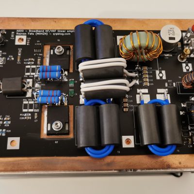
This design offers a practical solution for HF/low-VHF amplifier output filters, handles 600W and is designed to cover all amateur bands form 160m to 4m. It is a necessary accessory for the 600W HF/VHF LDMOS linear amplifier in order to remove any harmonic products and make the amplifier legal to use on the air.
Challenges
For this design I am assuming the signal used to drive the amplifier is clean and complies with legal requirements in terms of harmonics and IMD products. These filters are only designed to stop any additional harmonic products generated by a correctly functioning amplifier and to keep their level within legal limits.
As all modern RF power amplifiers use a “push-pull” design, the even harmonics (2nd, 4th etc) are generally already at a very low level, being cancelled out by a symmetric design. We only need to worry about uneven harmonics and the 3rd is the strongest and hardest to stop, so most filters on this board are optimized to achieve maximum attenuation for the 3rd harmonic of the lowest frequency signal.
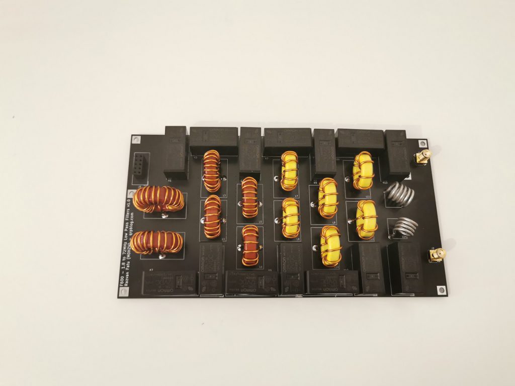
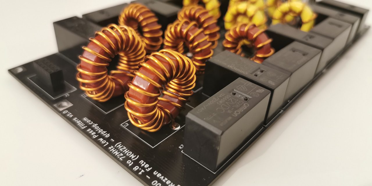
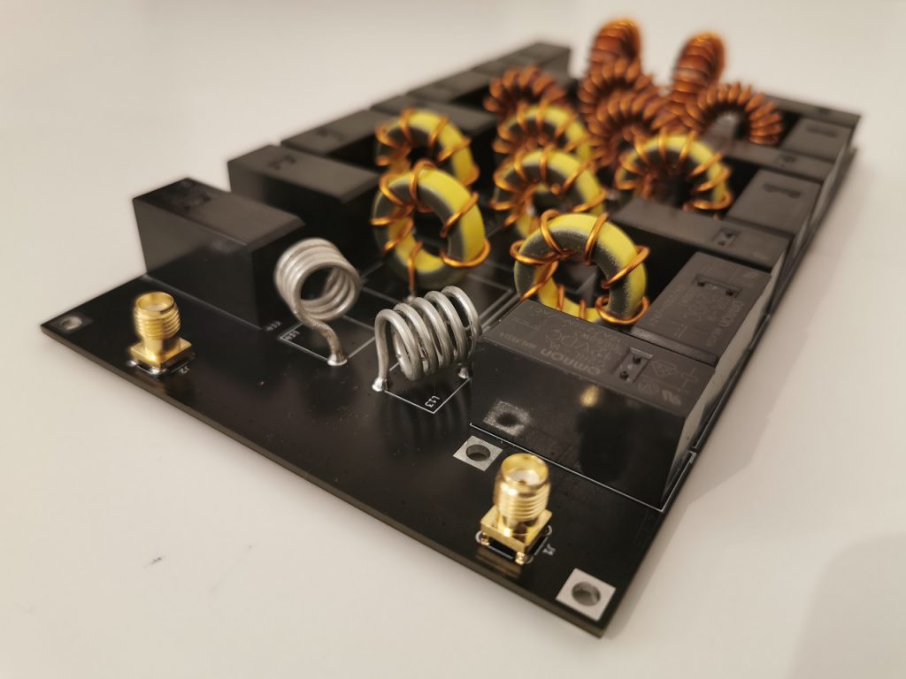
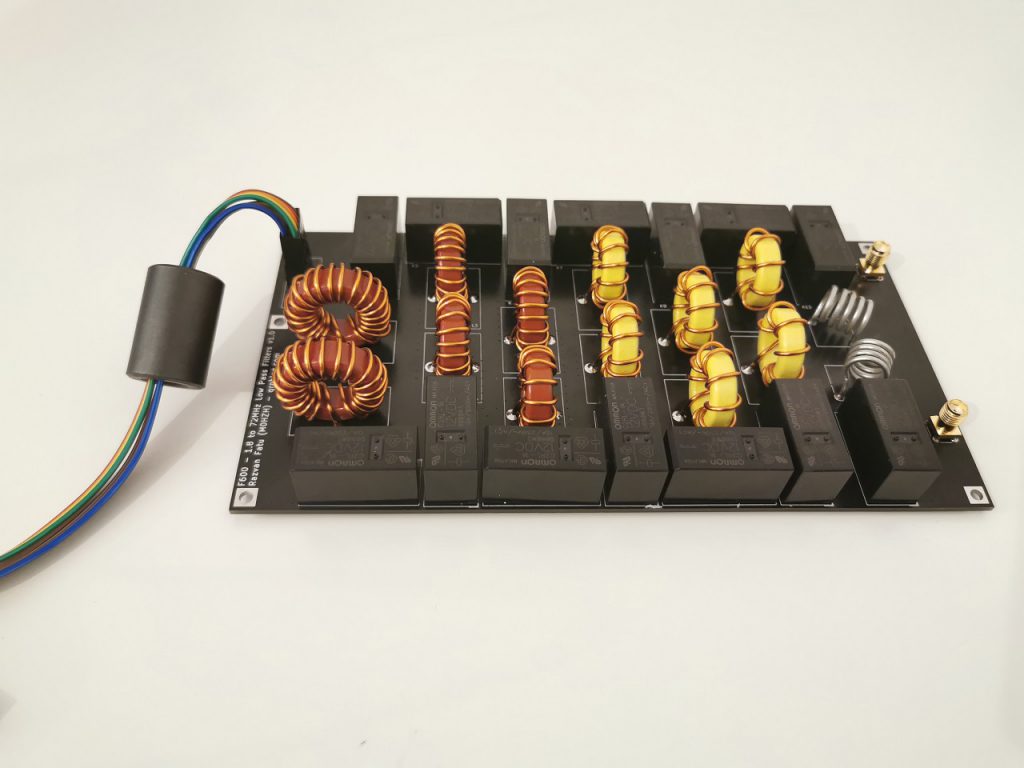
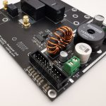
As this board is designed to be used with the A600 amplifier board, compatibility was one of the main design criteria. Same board size, same position of mounting holes as A600 v2 (or later), RF and control connectors on the same sides make this board easily stackable with the right spacers. Fitting 7 separate high-power low-pass filters with associated relays and large toroids while also considering all aspects of correct RF layout was a challenge, which resulted in the “interesting” positioning of the relays.
Schematic & filter layout
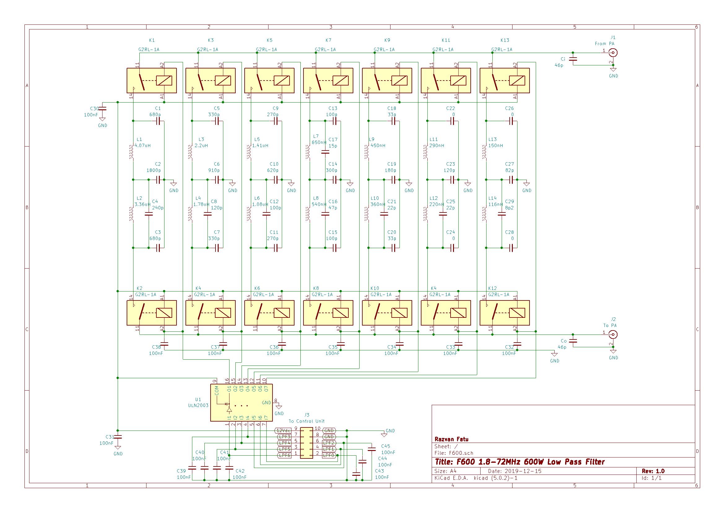
To achive the desired attenuation, a simple 5-pole Cebysev or Butterworth filter is not enough; a 7-pole filter would fit the bill but it requires too much board space.
My choice is to use a mixed topology with the second cell also forming a “notch” around the 3rd harmonic’s frequency. This offers similar performance to a 7-pole filter but uses 1 less inductor, which means slightly lower insertion losses (and a lot less work to assemble the kit). The filter shared by the 30m and 20m bands requires a different layout.
For design and simulations I’ve used an excellent free piece of software, Elsie from Tonne Software. Some of you may be familiar with it but if no, make sure to try it out when you want to design a filter. It allows you to tweak your design or it can generate filter schematics as well, you just need to input the desired topology and desired characteristics. I found the simulations very close to the real-world filters.
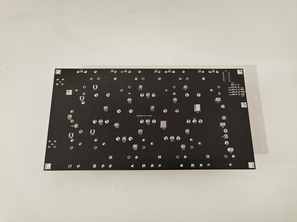
The Printed Circuit Board
The PCB traces and switching relays will have stray reactances that have to be taken into account when designing the filters. This particular board and relays have around 46pF parasitic capacitance on each side (Input and Output) which appear on the schematic as Ci and Co. These values can be lowered by avoiding to use ground planes near the RF traces, but this will increase RF radiation from the board (which is unwanted).
Insertion losses are quite low, however even 0.2dB of loss at 600W is almost 30W of heat that has to be dissipated in the toroids, PCB and capacitors. The board will need lateral airflow if it will be used on high duty-cycle modes.
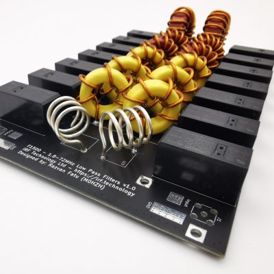
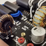
Inductors
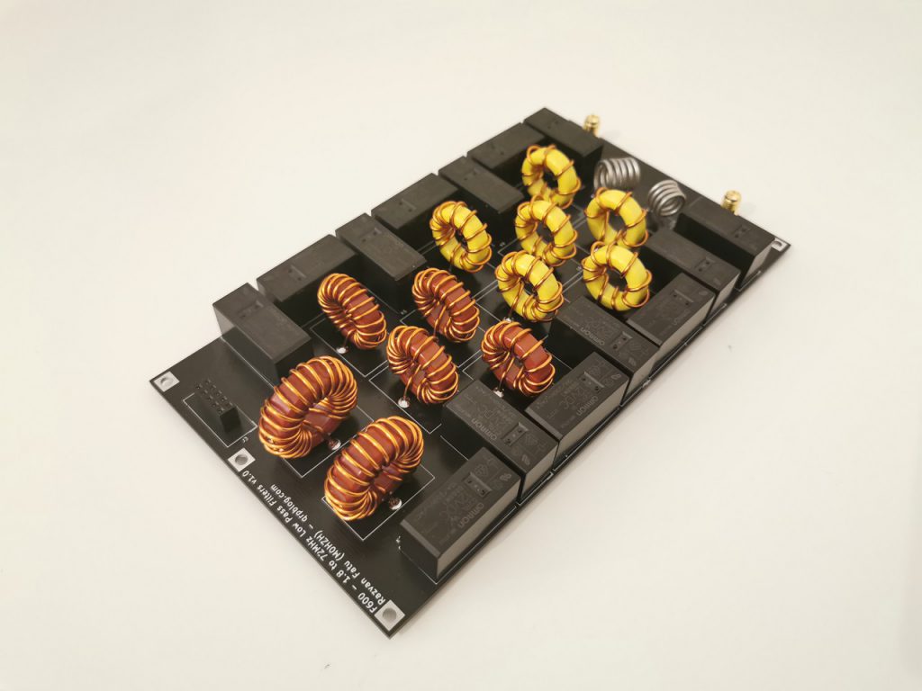
Adequately sized toroids are used for most inductors, along with 1.12mm diameter enamelled copper wire. The only exception is the 6m & 4m filter, where air core inductors made out of 1.5mm silver-plated copper are used instead. This offers higher Q and lower losses, but the magnetic field is not contained so positioning the coils for minimal coupling is very important.
See below a table of Amidon toroid types and number of turns required to achieve the required inductance values.
| Reference | Core | Value (uH) | Turns |
|---|---|---|---|
| L1 | T94-2 | 4.07 | 22 |
| L2 | T94-2 | 3.36 | 20 |
| L3 | T80-2 | 2.2 | 20 |
| L4 | T80-2 | 1.78 | 18 |
| L5 | T80-2 | 1.41 | 16 |
| L6 | T80-2 | 1.08 | 14 |
| L7 | T80-6 | 0.65 | 12 |
| L8 | T80-6 | 0.54 | 11 |
| L9 | T80-6 | 0.45 | 10 |
| L10 | T80-6 | 0.36 | 9 |
| L11 | T80-6 | 0.29 | 8 |
| L12 | T80-6 | 0.22 | 7 |
| L13 | air, d=11mm, l=12mm | 0.15 | 4.7 |
| L14 | air, d=11mm, l=9mm | 0.116 | 3.7 |
Capacitors
High quality, low-loss RF capacitors are critical for a high-power RF filter; if the manufacturer doesn’t specify the RF current rating it’s best to avoid.
You’ve probably seen filter designs with RF capacitors paralelled for higher current capacity; in many situations, this is not necessary. For the same manufacturer, product line, packaging and frequency, higher capacity usually means proprotionally higher current.
For example, a 1000pF Cornell Dubilier MC22 1000V capacitor handles twice the RF current vs a 470pF capacitor (roughly 3A vs 6A at 2MHz), so using two 470pF instead of a 1000pF won’t bring any real benefit. To achieve better RF current handling usually larger packaging is necessary, although not really available for this product line, as MC22 is the largest already.
For the lower bands (160m and 80m), high-quality large size MLCC capacitors of can be a good replacement, as they are available in larger capacities.
SMD packaging has a number of performance advantages over THT due to the lack of lead inductance.
Measurements
The filters have been tested thoroughly in simulations, with a VNA and then with 30 seconds on / 30 seconds off full power cycles. See below the VNA measurements for each filter, with markers around the main points of interest: lowest frequency used, highest frequency used and the 3rd harmonic of the lowest frequency used.
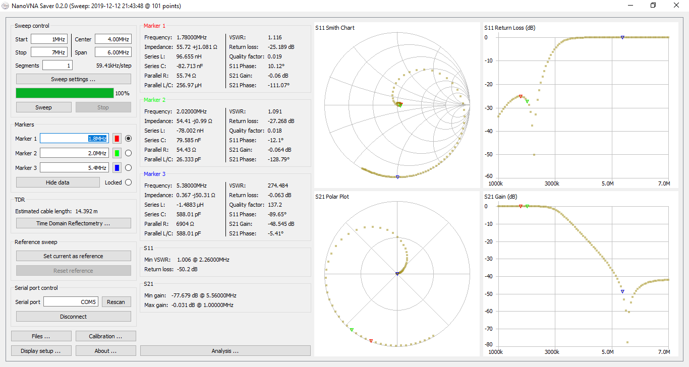
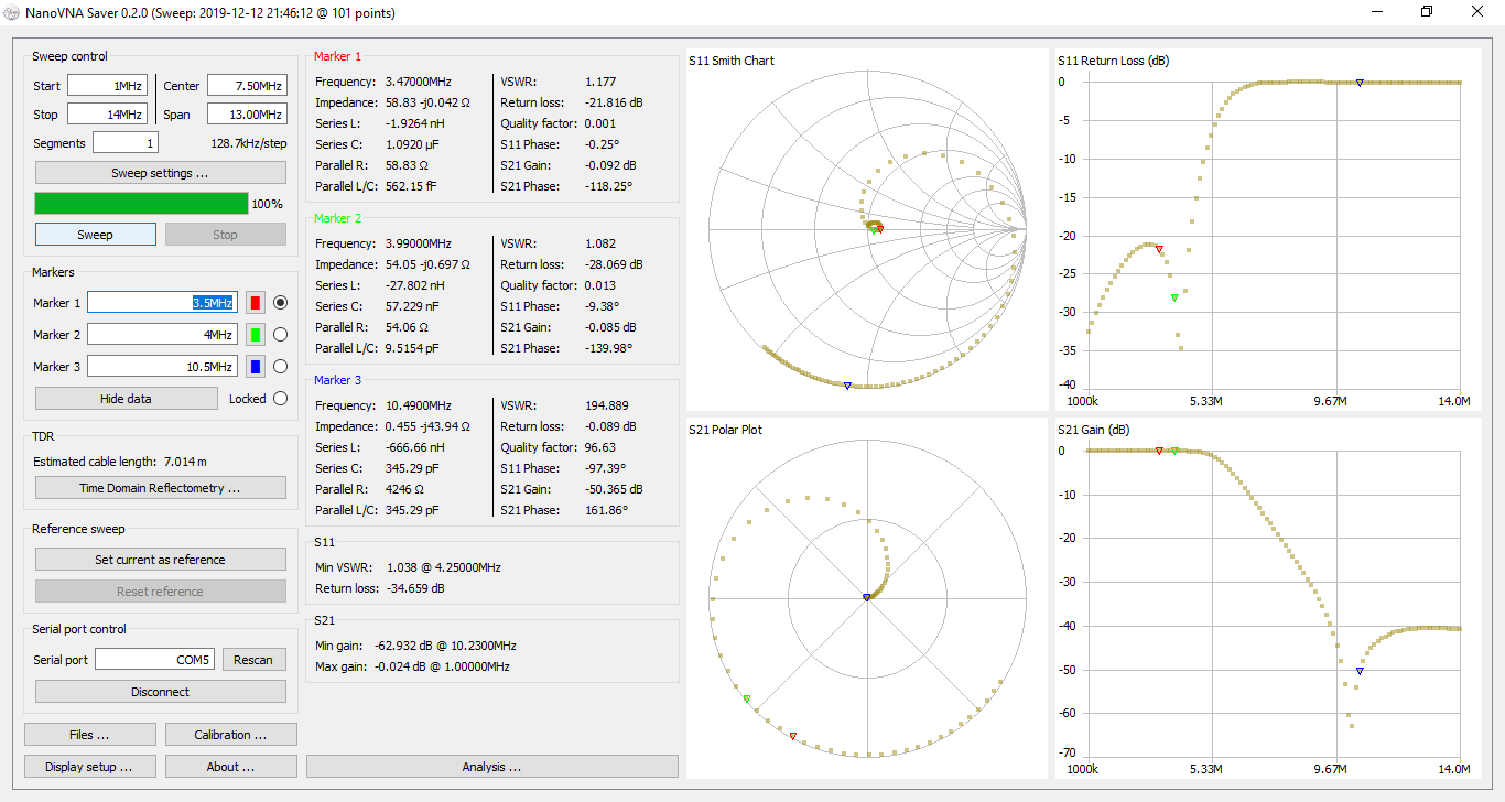
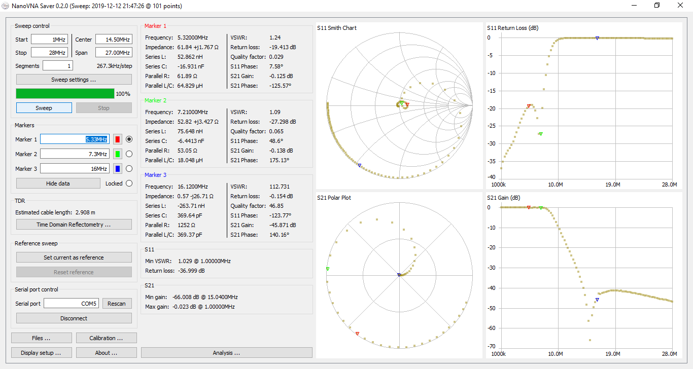
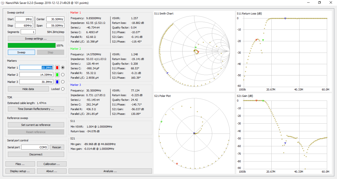
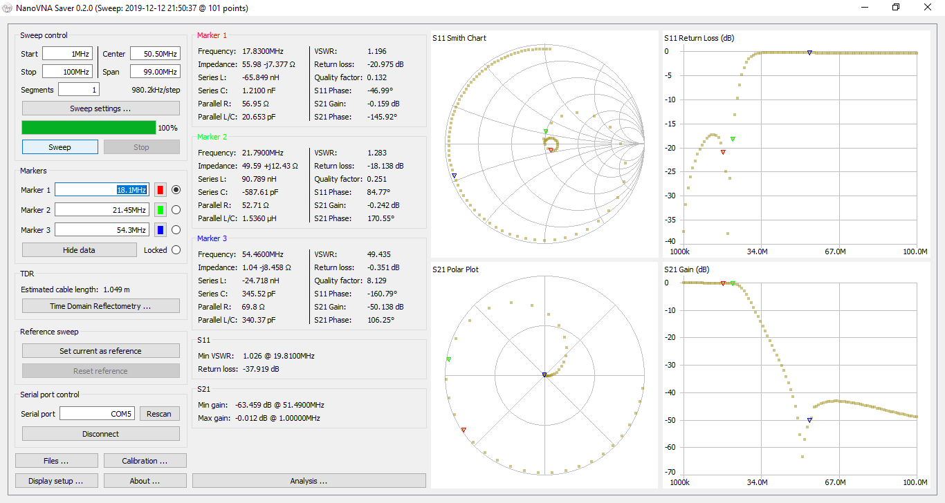
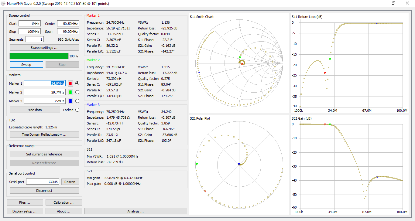
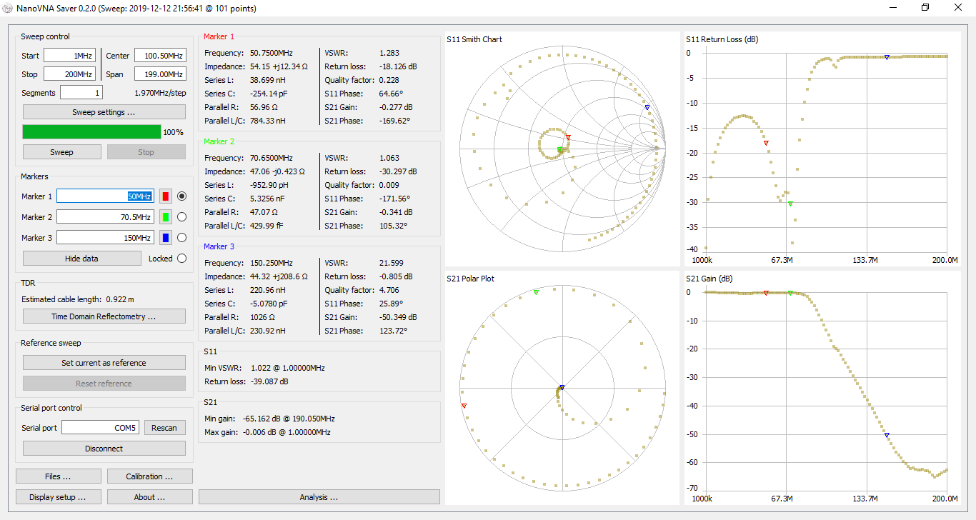
Insertion loss varies from 0.06dB to 0.34dB (in the 4m band), with a typical value around 0.2dB. The worst 3rd harmonic attenuation is -37.6dB (on the 10m band), with a typical value of -50dB.
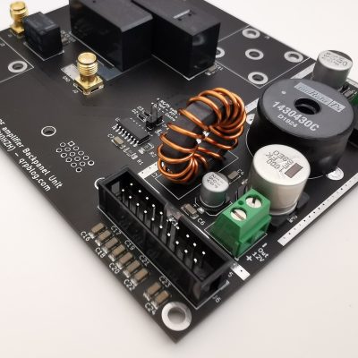
Control
The board needs a 12V/200mA supply and the filters are selected with TTL logic levels via the J3 connector. See schematic above.
The board allows selecting any number of filters at one time, so the logic circuitry needs to make sure only one filter (the correct one) is selected.
The F600 board is available in kit form in the shop area.

Hello Razvan,
I just ordered your F600 filter bank kit and eager to assemble it. What plans do you have for RX/TX relay circuit? Would you consider integrating it with the MCU controller (as opposed to a version 2 of F600)?
Hi Lance, thank you for the order. There is a Backpanel Unit in the pipeline, which will integrate with the amplifier Control Unit. At this point it is planned to include RX/TX switching, a few other rear connectors and a 50V>12V step-down regulator. Still working on the features list at this moment, but it should come soon.
Any linearity measurements if this is used as an input filter?
Can you better explain the application ?
This is designed to be handle 600W without introducing noticeable non-linearities.
pa0nhc : About the LPF kit :
I advise builders to FIRST solder all coils, and secondly solder all relais.
Reason:
Sometimes i needed not only to flow coil solder points on the PCB bottom side, but to be sure, also flow solder points on the PCB top side. The space between relais and coil soldering points is small. Touching relay housings is likely.
The OMRON relais are sensitive to deformation of the plastic housing. If the housing is only a little deformed (by heath of a solder iron) the relay blocks and will not switch. Check all filter in-out connections with an ohmmeter.
Pre-tinning coil wires :
REM : The silver plated coil wire is ALSO lacquered, and need also to be pre-tinned.
I found removing lacquer from wire ends difficult. But modern lacquered wire -can be soldered- with a HOT solder iron :
Cut excess wire.
Heath the bare copper tip of the cut wire end with a 420 degree Celcius solder iron, using a bit of resin core tin (and extra solder flow paste).
Wait until the wire insulation melts.
Keep giving more fresh solder tin and move the solder iron tip slowly towards the coil until enough wire is tinned.
Remove brown residue and check if all wire surface is tinned.
73’s, Nico.
So whats the price for everything ? What wattage iron will i need ? 73 Hank
I use and recommend a cheap “Quicko” T12 100W solder station (Aliexpress). Works well, much different cheap T12 solder tips available. 420C is no problem. The only negative thing is the strong QRM it makes on long wave frequencies (around 110kHz.).
I measured the LPF0 – LPF6 frequency characteristics using a NanoVNA. In my case (suggested modifications were not tested yet) :
LPF1 : The 3rd harmonic notch is at a to low frequency, about 10,25 MHz.
I suppose changing C8 to 100p will shift the notch to the correct frequency.
LPF3 : The 3rd harmonic notch for 14MHz is at a to high frequency.
Changing C17 to 18pF could possibly correct this.
Measure the frequency characteristics after modification.
See all other mods on my site : http://www.pa0nhc.nl
73’s, Nico.
Thank, Nico. There is a small variation in filter curves, depending mostly on toroid mix variation and winding. Also, the notches don’t have to match the 3rd harmonic exactly as there is enough attenuation anyway.
Razvan.
Hello Razvan, I purchased this LPF kit a month ago and now works fine. Great product! But I wonder if you have designed to optimize 6m band. In Japan, there is no 4m band but spurious level above 6m band is -70dBc. In my case, I need 10dB more reduction at 100MHz.
Hello! This is not specifically designed for maximum performance on 6m. “Push-pull” AB class amplifiers generally have low 2nd harmonic levels and -20dB of attenuation is more than enough to meet requirements in most countries; also high attenuation filters are harder to get right by kit builders without using proper measurement tools.
If you have a VNA I can suggest tweaking L13 & L14 coil spacing for better attenuation at 100Mhz, as long as insertion loss stays low. I will try to simulate a few improvements and come back with a better suggestion, feel free to send me an email so we can follow this up.
Razvan
Hello Razvan, I tortally agree with you. Actually I only need 20dB reduction for 2nd and 3rd harmoics. But I have a long story to get expected result. I have another LPF which is optimized for 6m. This works fine for 2nd harmonics but almost nothing for 3rd harmonics. I am suspecting internal component’s non lineartity or leakge. Your LPF is good for 3rd hamonics but not enogh for 2nd harmonics. I have a VNA, so let me try your suggestion. But unfortunately my SA is down now and I may need another month or so to try.