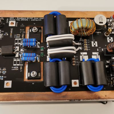
I have recently made available a new version on the A600 amplifier based on MRF300 LDMOS transistors. Here is the list of changes and improvements that come with v2.0.
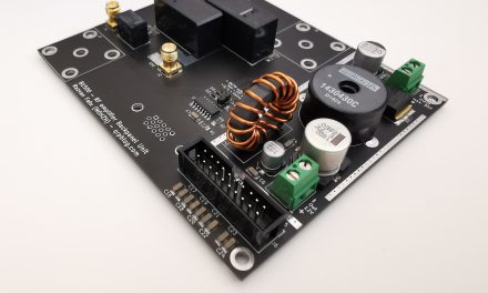
1. Redesigned and improved PCB
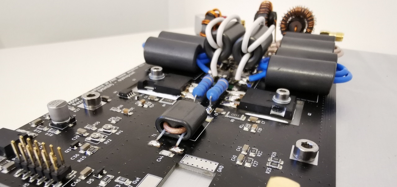
All components are now on the top side, while the bottom side is a continuous ground plane in direct contact with the heatsink. This improves the electrical ground even further and (together with the black coating) maximises thermal performance. It also allows for the thermal sensor and the temperature-compensating bias thermistor to be mounted as SMD parts directly on the PCB and not require additional heatsink mounting holes.
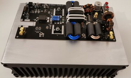
2. 70MHz band coverage
Thanks to slightly better layout of the input traces and the use of semi-rigid transmission line instead of coaxial in the output RF power transformers, the coverage has been extended to 1.8 to 72Mhz. A 4.7pF PCB capacitor at the input of the directional coupler improves performance & matching on 6m and especially 4m. Keep in mind in most countries 450W is way above the legal limit on the 4m band (!).
3. Easy-to-use bias circuit
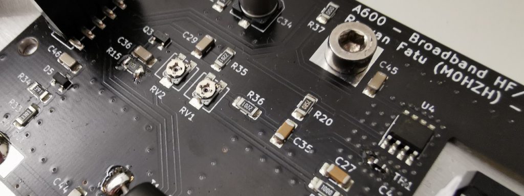
The bias circuit now uses the same 5V (5.36V more precisely) voltage regulator circuit that supplies power to the thermal sensor and the current sensor. There are only two trimmers that adjust the bias voltage from 2.2V to 3V for each transistor and they come pre-set to a safe value. Now you don’t need to pre-adjust the bias before installing the transistors and you cant destroy the transistors by accidentally setting the bias too high.
4. New RF drive sensor and expanded Sensor Port
New onboard circuitry measures the drive power and provides a proportional continuous voltage at the Sensor Port within the 0-5V range. This can also be used as a RF drive detector for a (separate) automated RX/TX switching (RF vox) circuit. The Sensor Port has been expanded from 7 to 12 pins now and also provides a +5V 200mA supply voltage than can be used to directly power measurement & protection circuitry connected to the Sensor Port.
5. Can be set up for high drive (up to 100W)
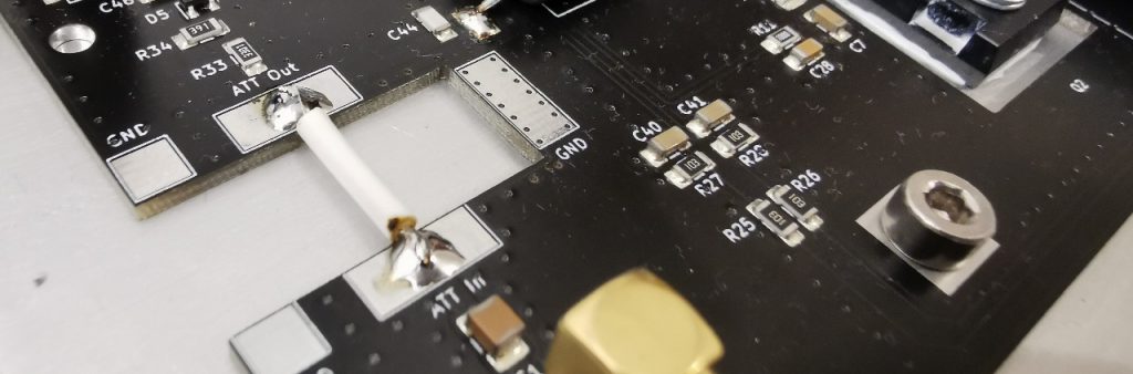
The PCB now has a slot for installing a high-power RF attenuator on the same heatsink so the amplifier can be driven directly even with 100W transmitters. ATC FA10975P03DBFBK or the cheap RFP1398 are good examples of 100W 20dB attenuators that would have to be installed for this purpose. Otherwise, a straight jumper is fine.
6. More accurate current measurement
The current sensor has been replaced with ACS713ELCTR-30A-T, which is unidirectional but offers twice the output voltage per A compared to the previous ACS712. This will allow more accurate current measurement when using modest resolution ADCs (like the 10-bit on some Arduinos).
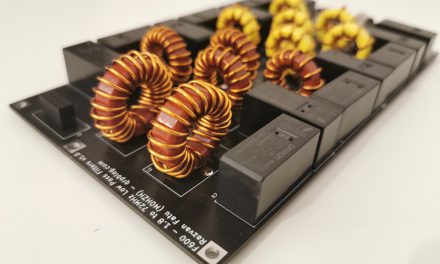
7. Onboard jumper for testing without a LPF
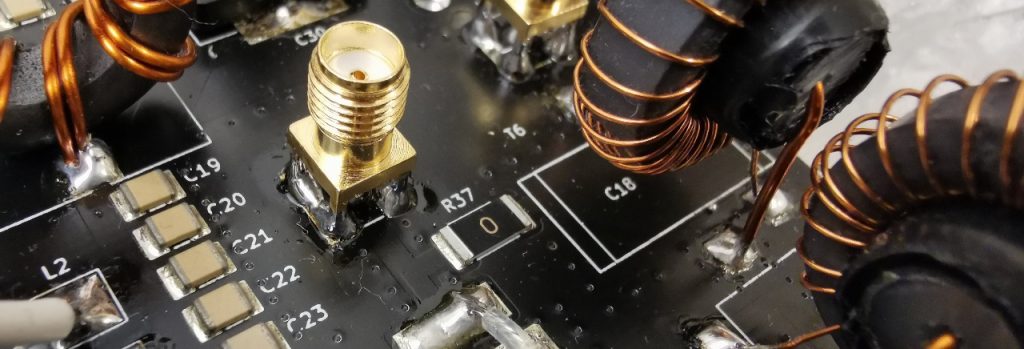
The module is now supplied with an onboard jumper (R37) that shorts the LPF ports. This will allow you to run the initial testing without having a Low Pass Filters board connected. Once you get things going, R37 will have to be removed and a LPF board connected to the J2 & J3 ports.

Greetings Razvan, I just received kit V1.2 in the mail and now see you have V2.0 designed. Do you have an upgrade path/kit planned to bring V1.2 to V2.0? Also looking forward to the LPF bank and controller 🙂
Hi Lance, at the moment there is no plan to upgrade v1.2 to 2.0, as the PCBs are different.
As you can tell from this article most of the changes are for convenience rather than performance. v1.2 works on 70MHz as well, but with slightly lower gain & lower maximum power; it’s still well over the 4m band legal limit in most countries (the 4m band is not available in the USA yet, by the way). The drive power measurement circuit can be added with a small separate board, if you need it.
Hi Razvan,
What type of RX/TX relay (model) would you recommend for this amplifier?
Hi Victor,
Omron G2RL-1-E-DC12 should be OK for output switching, I use the SPST version for the LPF. Make sure the control logic doesn’t allow switching the output under load.
Omron are perfect even with high power up to 70 MHz. See what W6PQL says about it
Hello I would like to use your AMPLIFIER MODULE for a fixed frequency project with 13.56 MHz fixed and vary the wattage output.
I am not using a Radio as the pre-amp so i need a linear pre-amp to vary the wattage input to your amp, i am amusing. what is the input wattage range need to operate your amp from a min to max out-put. into a 50 ohm load thanks
Hello. Great project, Razvan. Could you tell, if it’s not a secret, what type of semi-rigid coaxial cable do you use for the output transformers? 73! Greg SP5MI
Can I also order lpf and control board pcb’s only together with the pa kit?
Hi Kees,
PCBs are not available separately, only as kits. However, at the moment there’s a discount if you but all 3 kits at the same time ;). Just add all 3 to the cart.
Hello Rasvan,
I followed your A600 Project with interest from the beginning. It’s an very integer proper PA kit ! Thank you for sharing your ideas and practical details within this project !
I also build up an LDMOS amplifier with MRF300 as push pull design. It comes from a former BLF188 board from eb104.ru modified for MRF300 circuit implementation.
I did an attemp with the 1:9 TLT – transformer (original eb104 design) at output side with no stable results (low output power, high current and low efficiency).
After these results one question was coming up:
Why it should work with 1:9 TLT output transformer ?
For my understanding we have nearly 10Ohm differencial output impedance for MRF300. So 1:9 TLT gives a much higher broadband mismatching as using a 1:4 TLT transformation ?
Using this 1:4 TLT the results were much better (but not good at low band – 80mtr/40mtr).Really low current and nearly good output at 20 mtr (500W after bandpass filter, around 400W at 21MHz and 28MHz but only around 300W at 40mtr/80mtr independed from input power) I think there is a high mismatch at lower frequncies due to low impedance transfer (lower than the expected 40 Ohm). The drain currents are always in very low “no dangerous zone” (lower the 12A total current both).
Did you try 1:4 – TLT design for MRF300 push pull design at the begining of your project and after your results you go further with using 1:9 Transmission line transformer and optimization ?
I wouldn’t keep you in a long discussion session but your experience would be interesting for me.
73 and thank’s in advance
Stefan, DL9GRE
Hi Stefan,
Roughly, the output transformer ratio depends on supply voltage and output power. The two transistors can generate almost 2*Vdd peak-to-peak voltage in the primary; without going through all the calculations, for 50Vdd supply this will limit power output to about 400W for 1:4 and 900W for 1:9. That is why some builders use 53V or more to achieve 500W with 1:4 or 1000W with 1:9; however, keep in mind the maximum spec for MRF300 is 50Vdd as per the datasheet.
Output transformers will also have to have a good frequency response and to be compensated / matched correctly, but the basic calculations for ratio are mostly related to Ohm’s law.
Hello Razvan,
thank you for your reply. Okay, that what I take from your answer there no deeper concerning regarding mismatching at output („primary“) site.
It is more an fact of good compensation ideas and several practical attempts. That is what I get reflect in different experience reports, as well eb104.ru projects.
I‘m using 53V supply voltage btw.
The other facts about voltage transfer and current are known so far.
1000W out with 1:9 TLT and 2xMRF300 is an outstanding result.
73
Stefan, DL9GRE
Of course transformer matching should be observed, but that varies from one design to another and even with PCB layout or exact parts specifications. It is one of the more refined aspects of amplifier design.
1000W is not achievable with a pair of MRF300 (at least, not at room temperature), the comment was about the limitations of transformer ratios on output power.
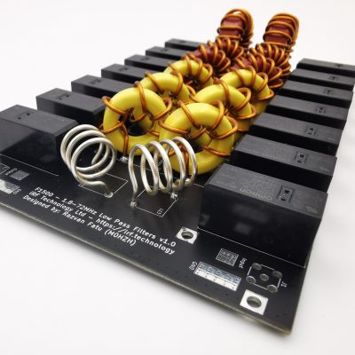
I have A600 PCB V2.1 and an LPF 1.0 set in use, which i switched by hand.
I placed a few modifications on my site. See http://www.pa0nhc.nl
WARNING :
When changing the transmitter to a higher frequency band :
=>> FIRST check that the LPF is NOT still set to a lower frequency band. <<=
When the LPF is set to a lower band than the transmitter, and applying drive power, Q2 is IMMEDIATELY damaged, gate shorted to source.
Bye bye 54 Euro.
Symptoms : no idle current, and only a few watts output.
73's, Nico.
Hello Razvan
My name is Geoff ZL3PX and I am very interested in purchasing the A600 amp a couple of questions can you supply me with one already built/constructed the reason being I have Parkinsons which causes me to shake so soldering is out of the question
I await your reply
Hello Geoff, thank you for reaching out.
Unfortunately at the moment I can’t offer completed modules, just the kits.
Razvan
Hi Razvan,
first of all very good job for this RF PA.
Now, I have a question about the output transformers: based on how they are connected on the schematics, it looks like they are 4:1 Ruthroff transformers with alternate reference (instead of the standard unbalanced-unbalanced Ruthroff, so having common GND as reference) and not 9:1 coax transformers.
For reference, I see these paper: Figure 3. A coaxial realization of the Ruthroff 1:4 unbalanced-to-unbalanced transformer ( https://www.allaboutcircuits.com/technical-articles/a-brief-introduction-to-ruthroff-transmission-line-transformers/ )
The number of turns should only affects the C coupled (e.g. bandwidth), not the input/output ratio, based on your final realization.
May I kindly ask you to plot the measurements of such transformer done with the VNA if any?
Regards