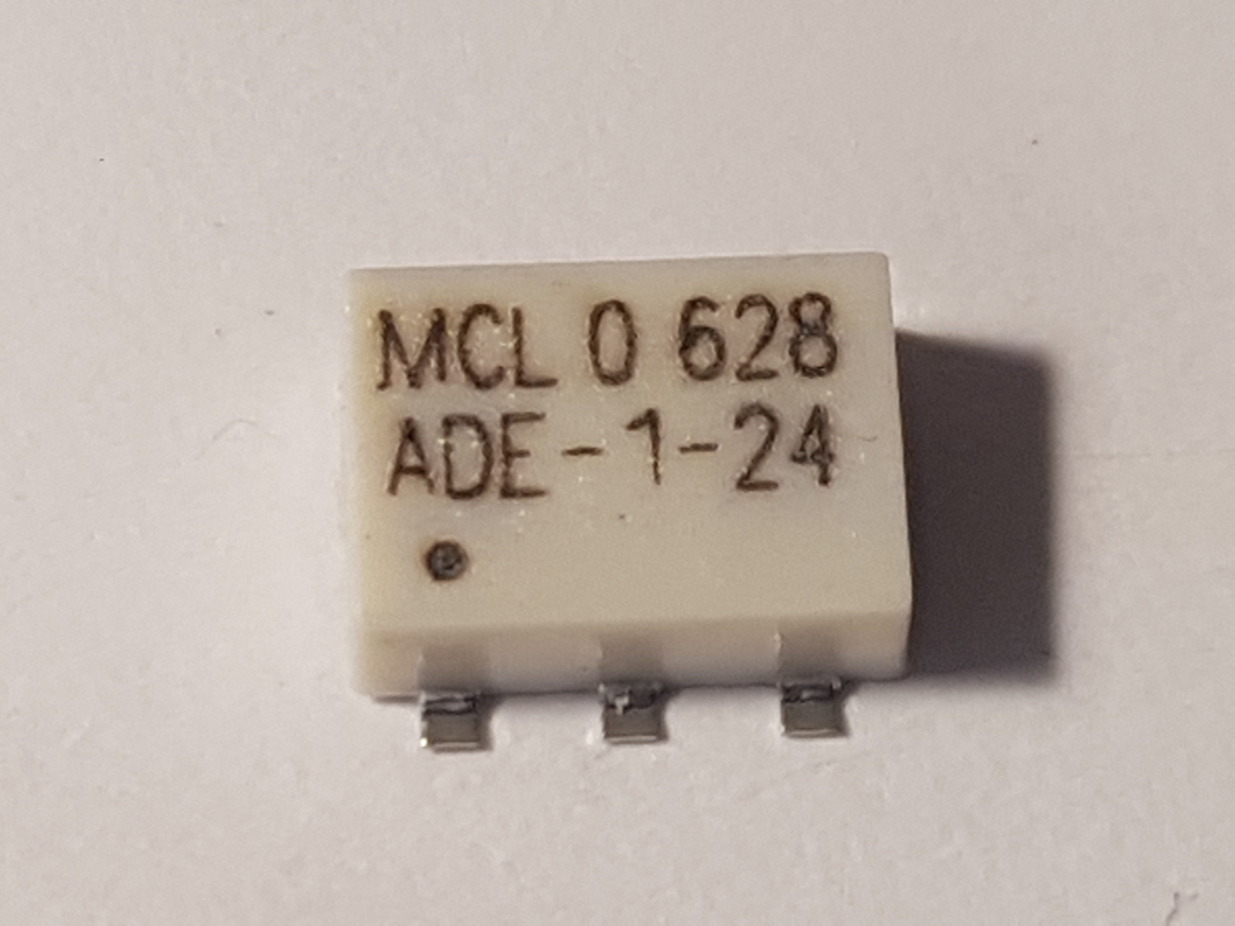
ADE-1-24 are double-balanced RF mixers that can be easily found all over eBay, Aliexpress and a few other websites. They are usually available for attractive prices and sometimes might be advertised simply as “ADE-1”.
However, the manufacturer claims that ADE-1-24 is a custom version of the Mini Circuits ADE-1 mixer, built on order for a customer and not necessarily identical to the ADE-1. There are no official specs published for the ADE-1-24. All of the ones available seem to have the same manufacturing date code 628, which means they were manufactured in the 28th week of 2006.
The case and pinout seems to be identical to the ADE1. A quick multimeter measurement showed ~0.1ohm between pin 1 and 6, pin 3 and 4, a diode drop of 221mV @ 1.7mA between pin 2 to 5. Pin 1, 4, 5 are not internally connected.
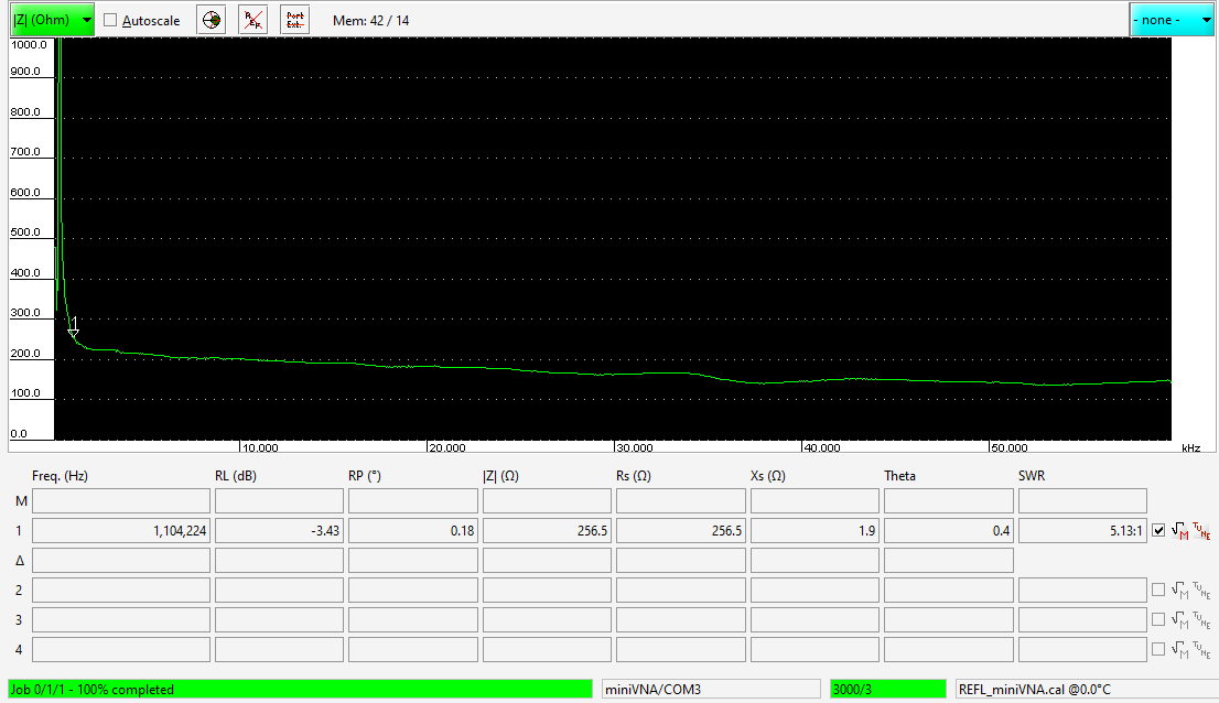
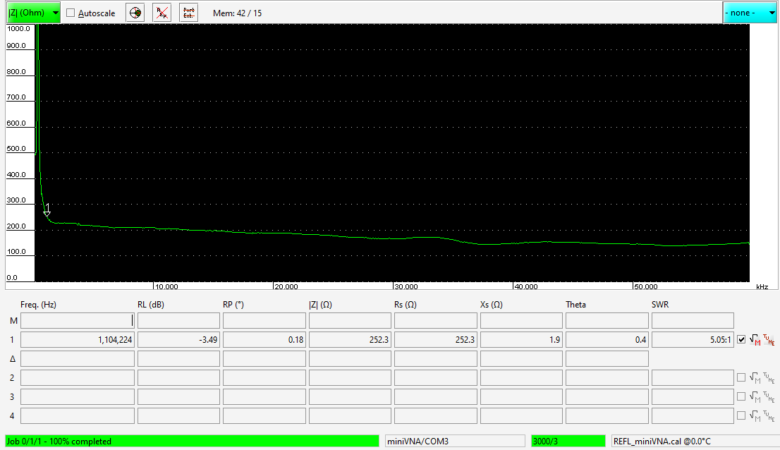
The spec sheet for the ADE-1 says 0.5-500MHz LO/RF range, +7dBm LO level, 5dB conversion loss, 55dB isolation and 15dBm IP3. An easy check was to test input and output impedance with my homebrew HF Arduino VNA . Unfortunately this is designed for work up to 60MHz so I can’t check it throughout the full range of working frequencies, but it gives us an idea if the ADE-1-24 matches the ADE-1 specs at least for HF equipment.
These are the sweeps for 0.1-60MHz @ +10dBm on the LO (1-6) and RF (3-4) ports.
As you see, it looks like these act quite predictable from 1MHz upwards, with a typical impedance of over 200ohm. I guess they can safely be used down to 500kHz, albeit with slightly reduced performance. The next test is to actually use one in a HF upconverter and see how it does.
.
Ampleon has launched the ART2K5TPU LDMOS RF power transistor, offering a 2.5kW output and 1-400MHz…
Icom has just announced the IC-905 SHF SDR transceiver that covers 144MHz, 430Mhz, 1.2GHz, 2.4GHz,…
Icom ID-52 is the latest VHF/UHF D-Star color screen & Bluetooth handheld transceiver released by…
This is an amazing hobby and has many sides to it, but as anything it's…
The B1500 RF amplifier Backpanel Unit is designed to sit between a LDMOS RF amplifier…
The new Icom IC-705 should be available starting April 2020, with a MSRP of 124,800…
View Comments
Hi Razvan,
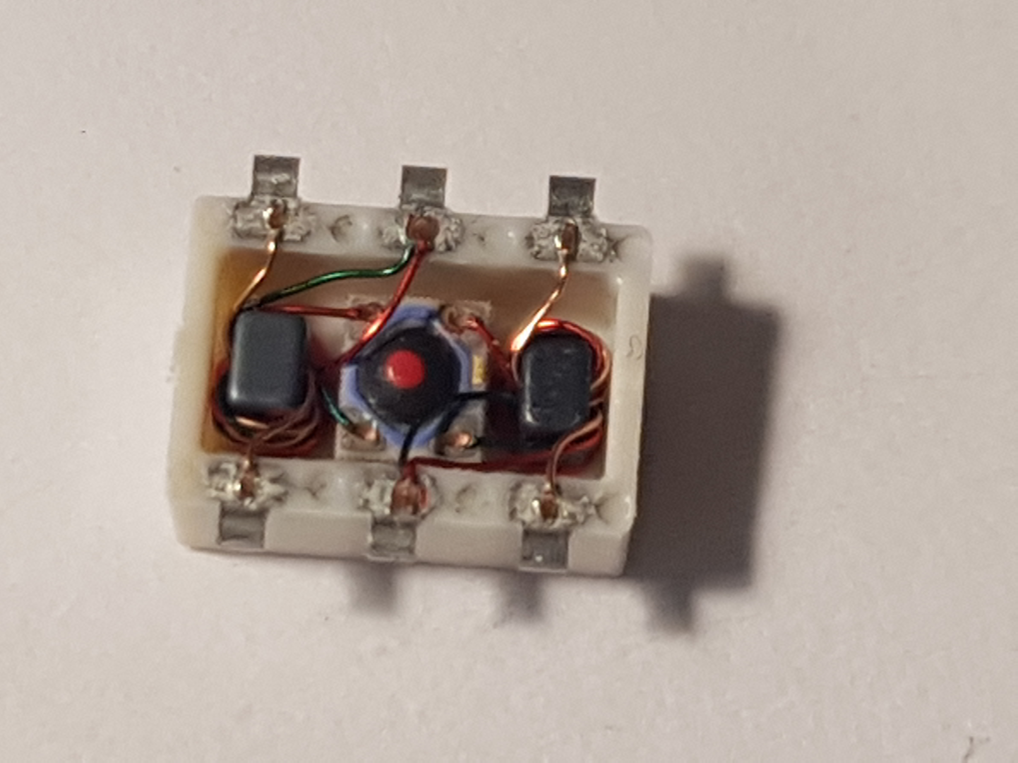
In fact, this mixer has a mirror image footprint with respect to the original ADE-1
this means that:
pin 1 and 6 are swapped
pin 2 and 5 are swapped
pin 3 and 4 are swapped
Testing shows similar specs to the original ADE-1 (taking the mirror footprint into account)
I'm using these im several Bitx receivers.
Tell me what you think.
Regards,
Han,
PA0JEN
Indeed the internal winding seems to be reversed, but this makes no difference in the way the mixer works, from my point of view.
Hi there ! waiting my ADE 1-24 (I did same mistake as others ) order to come.
As far as I can see in the photo , not 1-6 and 3-4 reversing is the main problem but 2-5. As original ADE1 specs tell us , the IF port and RF port should be on same transformer but in the photo they are opposite. so LO port becomes RF and viceversa.
If the technical specs are almost identical , I do not mind to use them (I ordered 4 of it and will crack open one of them too).
Will keep you posted once I get my hands on it. Thaks Razvan for shedding some light on this matter.
Gabriel yo8rxp
Hi Gabriel,
Yes, Han pointed that out to me. The real-life implication is that in a typical application (single-ended ports) you will get slightly lower LO-RF isolation (more LO will leak towards the antenna) but slightly better LO-IF isolation. The levels are very low anyway (around -60dBc for HF), but i think it's actually a good thing as it means less spurious LO in the IF chain. LO leakage towards the antenna port is not something to worry about, the level is very small and it would normally be stopped by the input BPF.
Cheeers,
Razvan M0HZH / YO9IRF
Hi, I read the blog and I have the same problem. Would anyone kindly have a schematic to fit it as an original ADE-1? Thanks and 73